
DFA – Simple Mechanical Assembly Techniques for Plastic Parts
Design for assembly (DFA) is a big subject, and it’s easy to get lost in all the assembly options out there. In general, though, DFA is the process of designing parts or products with ease of assembly in mind. This can mean reducing part count or designing specific assembly features into parts, all with the goal of keeping assembly time and costs as low as possible. But here’s a little side note on DFA before we dive into a few cost-effective assembly techniques:
In my mind, good design for assembly must strike a balance between cost reduction and product aesthetic appeal. Many engineers focus so hard on reducing assembly costs that they sacrifice the aesthetic appeal of the product to a point where it could impact sales numbers. On the other hand, designers can get so carried away trying to make a product 100% aesthetically perfect that they are unable to share their design with the world because it is too costly to manufacture. In many cases, getting to 90% from an aesthetic standpoint and reserving that last 10% for DFA can make the difference between a product that launches and one that fizzles out.
Okay, I’ve said my piece. Now let’s run through a brief overview of a few mechanical assembly techniques for plastic parts. I’ll also highlight some basic engineering design best practices and aesthetic tips for each.
Cantilever Snap-Fits
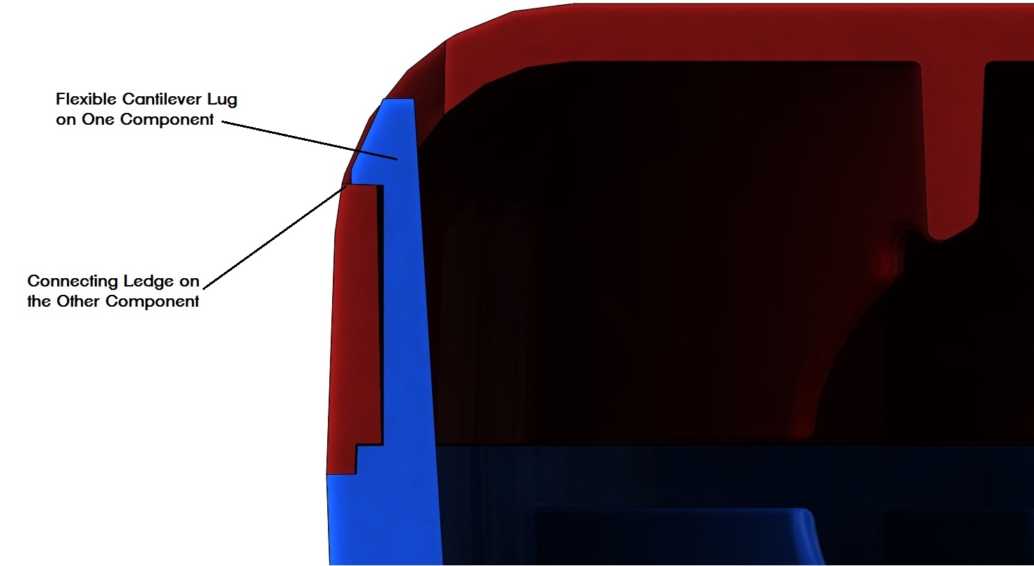
Snap-fits are a cost-effective addition to a design that makes assembly, literally, a snap. If appropriate for your design, consider designing in some form of snap-fit which will allow you to simply snap components together by hand. There are several different types of snap-fits, but in this article, we’ll just discuss Cantilever Snap-fits. As the name suggests, this type of snap-fit incorporates a flexible cantilevered lug on one component and a ledge or undercut on the other component for the lug to snap to, as shown in the image below.
Engineering Design Best Practices for Cantilever Snap-fits:
- If you can, consider designing the snap-fits in a way that avoids requiring slides (aka side action) in the plastic injection mold to help keep mold costs down.
- To maintain constant stress distribution over the length of the lug, make the lug slightly tapered as shown in the formula image below.
- Follow the basic formula shown below when designing the lug, where t is the starting thickness of the lug, l is the length of the lug, and h is the amount of interference of overlap. An easy way to back into the appropriate numbers is to make t equal to or slightly lesser than the wall thickness of your part. Then decide on how much overlap (h) you’d like and run these numbers through the formula to determine the length l.
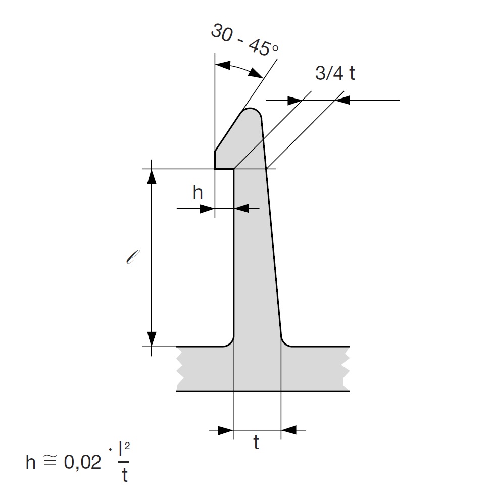
- Using the formula, experiment with these numbers, keeping in mind that the more you increase the overlap (h) the more the cantilever lug must bend during assembly, to come to a length l that works for your design,
- Consider discussing your design with a materials expert to make sure your cantilever design will work well with the materials you’d like to use for your production parts.
Cantilever Snap-Fit Aesthetic Tips:
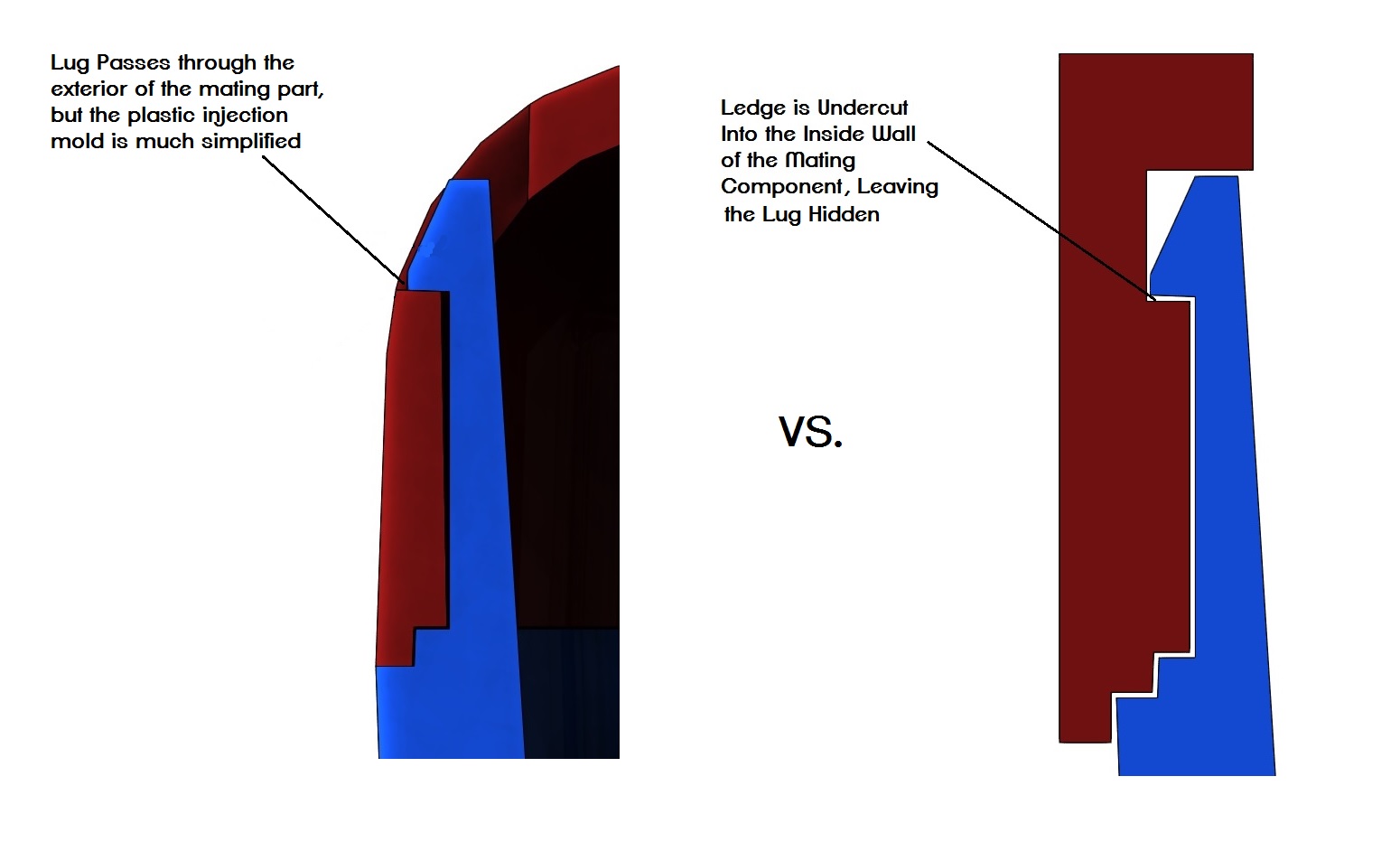
- Snap fits that pass all the way through a part can have a big impact aesthetically but it is possible to design them so the mating ledge portion is an undercut in a component as shown in this image below. However, incorporating undercuts like this into a part can dramatically increase tooling costs.
- Snap-Fits allow for assembly of dissimilar materials which is something not easily done with other assembly techniques like chemical bonding or sonic welding. This can add interesting aesthetic, tactile, and engineering properties to a design.
Mechanical Fasteners, aka Mounting Bosses
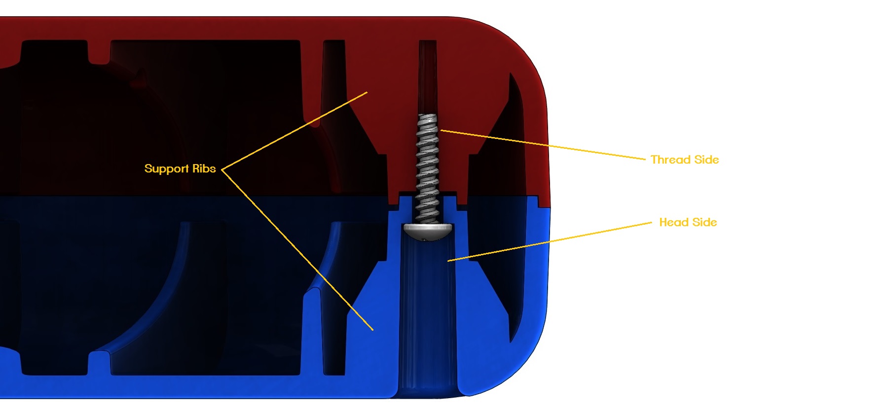
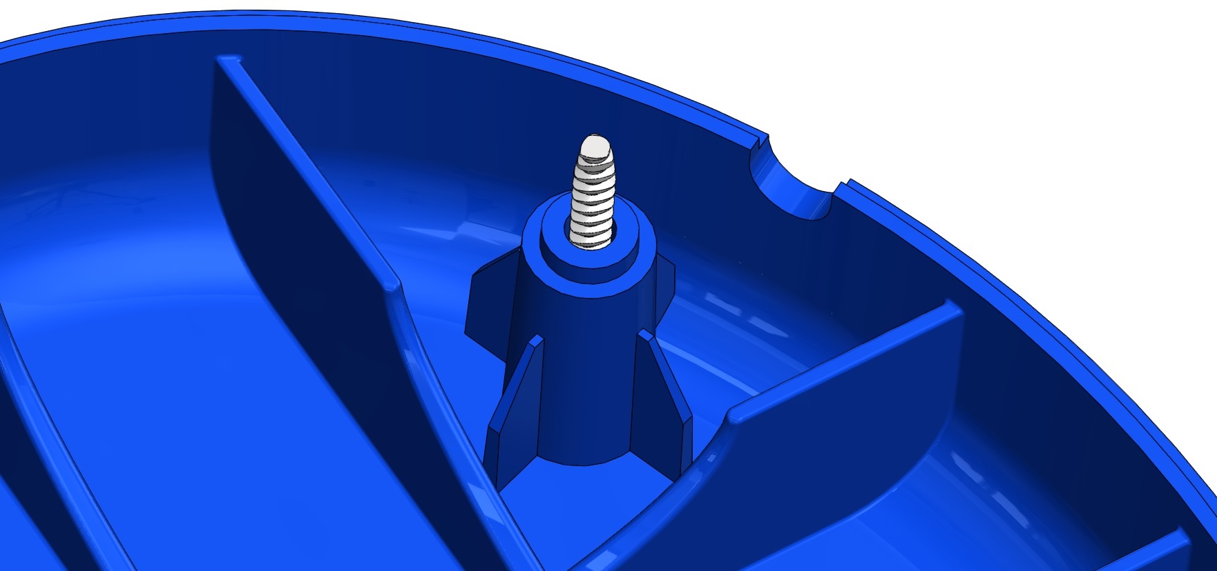
Mechanical fasteners, sometimes called mounting bosses, are features that are built-in to plastic components that allow you to use off-the-shelf thread forming or thread cutting screws to assemble the components together. A thread forming screw just deform the material, forming threads in the process. On the other hand, thread cutting screws physically remove the material. Mounting bosses have a head side (typically a recessed area where the head of the screw lies) on one component and the thread side on another component, as shown in the image below. Just as with snap-fits, mounting bosses allow you to join dissimilar materials if that’s something desired or required for your design.
Engineering Design Best Practices for Mounting Bosses:
- Get to know the physical properties of your material, particularly the material’s modulus of elasticity. This sounds tough to determine but really a simple google search for a material’s modulus of elasticity till provide the answer. Determining whether to use a thread-forming screw or a thread cutting screw depends on this modulus value. In general, if your materials modulus of elasticity is below 1500 MPa use a thread forming screw. If the modulus of elasticity is above 1500 MPa use a thread cutting screw.
- To determine the dimensions of your mounting bosses, first determine what size screw works best for your design both aesthetically and functionally, then use these formulas to design the thread portion:
- The hole diameter of the thread portion of the boss should equal the pitch diameter of your chosen screw. A screws pitch diameter lies in between its major diameter and minor diameter, as shown here:
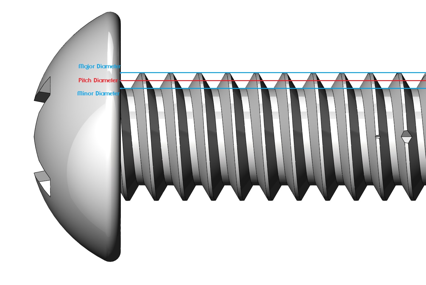
- The outside diameter of the thread portion of the boss should be about 2.5 times the outside diameter (major diameter) of your chosen screw
- For added support on the head end of the boss and to help the threaded portion of the boss resist cracking, add thin support ribs as shown here:
Mounting Boss Aesthetic Tips:
- Mounting bosses can have a less intrusive effect on the aesthetics of your part as all you’ll see is the reveal of a screw head.
- Treat the screw head as a unique aesthetic feature rather than looking at it as a mechanical feature that is just plopped into the design. Be intentional about placement of the bosses to create either an equally spaced or uniquely shaped pattern; or going with a screw with a unique finish (like black oxide or brass/bronze) can give your design a more refined look.
A Note on Lips & Grooves
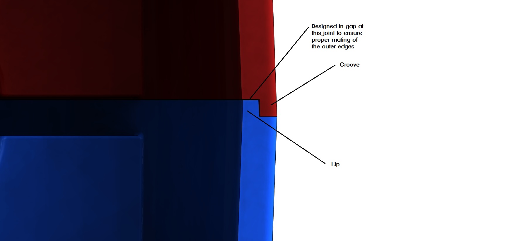
Typically, these types of mechanical assembly designs are used in conjunction with a lip & groove design which keep the mating parts perfectly aligned with each other. This is a very simple system to add to mating parts and it consists of a lip on one component and a corresponding groove on the other component.
Engineering Design Best Practices for Lip & Groove:
- Ensure proper draft angles and gaps are designed into the lip and groove system to make sure the two parts don’t interfere with each other
Lip & Groove Aesthetic Tips:
- Just make sure the bottom faces where the lip and groove meet have some gap dLip & Groove Aesthetic Tips:esigned into them so they don’t bottom out before the outer edges of the parts. This ensures you don’t end up with a larger gap between the mating parts after assembly.
Conclusion
There we have a brief overview of just a fraction of the assembly options available to product developer. One of the biggest benefits of the mechanical assembly techniques discussed in this article is they give inventors and start-ups the ability to assemble parts on their own, which comes in handy when just starting production and money is tight. So, if it’s appropriate for your design, I recommend employing one or more of these techniques to help keep your product assembly costs down.
Here are links to a few resources for you to check out to further your study on these and similar assembly techniques:
http://www8.basf.us//PLASTICSWEB/displayanyfile?id=0901a5e1801499d2
http://web.mit.edu/2.75/resources/random/Snap-Fit%20Design%20Manual.pdf
http://fab.cba.mit.edu/classes/S62.12/people/vernelle.noel/Plastic_Snap_fit_design.pdf

Eric Haddad
Owner/Chief Problem Solver, Dimensional Fidelity
Dear sir.
Good afternoon.
i want to know about the 2 ways and 4 ways locator used in plastics design for component location.
Hi Rajeeva, That’s a great subject. Please give me a chance to put together some info for you or put you into contact with one of our partner engineers.
Meanwhile, you can check this video out which explains the basics. https://www.youtube.com/watch?v=C_vqMerH-oQ
Very helpful information ..Thx
For Cantilever Snap-Fit, as you mention “design them so the mating ledge portion is an undercut in a component ” . Normally how depth of the groove can be if i just use forced demoulding method. (ABS product)
Hi Paul, I would recommend writing the author, Eric Hadaad for this info. This was a guest post by him. I’m sure he would be glad to help out. You can find links to his website etc. on his profile at the bottom of the article. Please let me know if you have any problems contacting him.